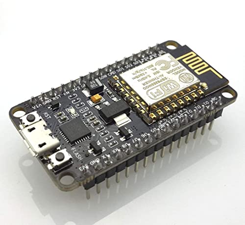
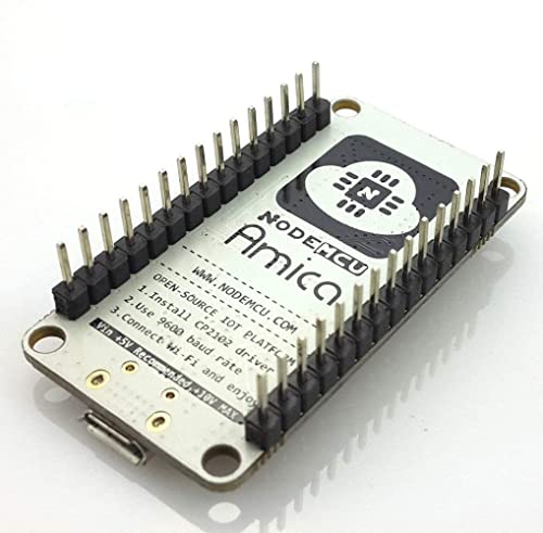
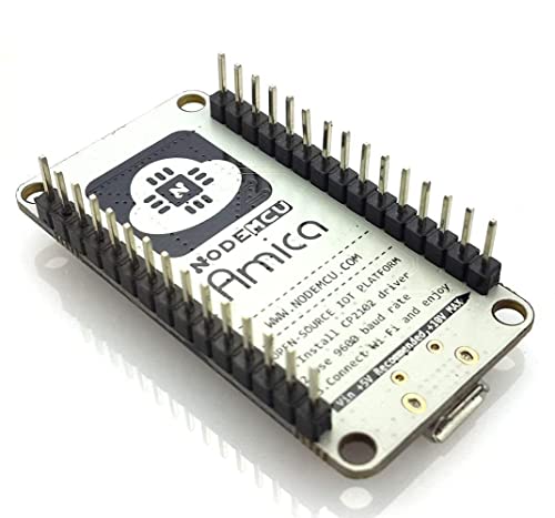
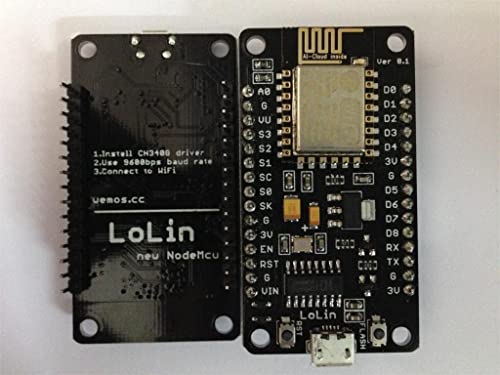
Lolin NodeMCU ESP8266 CP2102 NodeMCU WIFI Serial Wireless Module
★★★★★
(13 customer reviews)
₹699.00 Original price was: ₹699.00.₹429.00Current price is: ₹429.00.
Added to wishlistRemoved from wishlist 0
Last updated on August 19, 2024 1:07 am
- Esp8266 cp2102 nodemcu lua esp-12e wifi serial wireless module
- Built-in micro-usb, with flash and reset switches, easy to program
- Full I/o port and wireless 802.11 supported, direct download no need to reset
- Arduino compatible, works great with the latest arduino ide/mongoose iot/micropython
- Weight: 8.5 gms
,
Specification: Lolin NodeMCU ESP8266 CP2102 NodeMCU WIFI Serial Wireless Module
|
13 reviews for Lolin NodeMCU ESP8266 CP2102 NodeMCU WIFI Serial Wireless Module
4.0 out of 5
★★★★★
★★★★★
7
★★★★★
3
★★★★★
1
★★★★★
0
★★★★★
2
Write a review
Show all
Most Helpful
Highest Rating
Lowest Rating
Add a review Cancel reply
Related Products
Added to wishlistRemoved from wishlist 0
59%
Added to wishlistRemoved from wishlist 0
30%
Added to wishlistRemoved from wishlist 0
71%
Added to wishlistRemoved from wishlist 0
43%
Added to wishlistRemoved from wishlist 0
45%
Added to wishlistRemoved from wishlist 0
45%

Lolin NodeMCU ESP8266 CP2102 NodeMCU WIFI Serial Wireless Module
₹699.00 Original price was: ₹699.00.₹429.00Current price is: ₹429.00.


Vishwas Kumbhakern –
These things are awesome. I am currently running 3 of them with a small 64×128 OLED display and a DHT22 sensor in different places in the house. All this built using the Ardunio IDE. I have also added some NTP code I found on the web and now each board syncs up its clock using NTP, so it’s almost like having an RTC onboard (as long as you have internet connectivity, at least one time when you power up or reset the device). One of the most awesome features is being able to use the ArduinOTA package so that I can now make code updates wirelessly over wifi after burning the initial code into each board. There are only a few reasons that I would maybe use an Arduino board instead of these: Analog inputs – this has just one built in. Most of my analog input sensors already provide SPI or I2C interfaces, so that’s not an issue for me. You may also opt for Arduino if you absolutely need a 5V device (these are 3.3V) or for something battery powered where you’d want the lowest drain. Not sure yet if I can shut off the wifi radio in this guy to achieve similar low-power useability but for 90%+ of my projects, this has just become my go-to board. Note that the one I got from HiLetgo seems to be better than two other ones I got later from another seller. The HiLetgo one can be programmed at a full 921600 baud over USB, where the ones from the other seller can only be programmed reliably at 115200. This could be just luck-of-the-draw and probably they all come from the same factory and it may have just been a batch of less precise processor crystals or who knows what. The difference in programming speed isn’t huge, so no big deal. Overall, I am very pleased with these boards. I’ve attached a pic of my temperature/humidity sensor project. Uses just a NodeMCU, a breadboard, an I2C OLED display, a DHT22 sensor, a 10Kohm resistor and 7 jumper wires. I can access each one of my 3 boards through any browser to get the readings off of it. You could get rid of the OLED and 2 jumper wires, if you just want to be able to read your data through a browser.
– Quick follow up: I just got 3 more from HiLetgo and they all can be programmed at full 921600 baud, so FWIW, the HiLetgo “brand” appears to be better than the batch of 2 I got from a different seller, which could only be programmed reliably at significantly lower speeds though they still appear to run code fine after programming. I still love these NodeMCUs 🙂
– Another follow up: I have created a githup repo (search github.com for “esp8266_arduino_temperature_nodes”) with the source code. It’s a bit of a hodge podge since it’s just experimental as I play with this board’s capabilities. (update: added ILI9341 TFT display, see pic) Hope somebody finds it useful.
Haise –
Hi! Lolin Nodemcu dealer. This is Sagar Sahoo. 2 days earlier I requested a refund for your product, due to it’s improper functioning. But soon I realized it was working properly and my internet signal was weak. So I returned another IC (L298N) instead of Nodemcu. Because my L298N was cooked due to high current supply. Now I have intimated the fact to you via this message. Sorry from my side.
⚡ Pushpendra Singh Patel ⚡ –
Works like a charm after flashing the Arduino code
Daniel –
I have over 100 different microcontrollers that I use and have tried for various projects. There is never a one-size fits all, but this board has one primary advantage, the price. If you are familiar with the variety of boards out there one thing you probably know is that the more features you want, the higher the price. Many boards I have used that have built-in Wi-Fi, USB programming and a host of ports can cost upwards of $20.
Right out of the gate, this board supports a handful of ways to program it. The two most popular (in my opinion) are Micro Python and the Arduino IDE, both of which have great support. Once you install the driver, it appears as a USB device and is easily programmed. This makes it a great startup board for any beginner as well as a go-to board for advance usage.
The Wi-Fi is easy to use and reliable. I have had success with it connected it to various cloud services (did tests with Adafruit IO and Arduino Cloud).
Some have complained that the port assignments do not match the board. This is true and untrue. If you understand the difference between Arduino port assignments and how manufactures assign (pin) numbers to their GPIO ports then you will understand why this is different, however, to use the board you do not need to understand any of this. When you install the board driver in the Arduino IDE, you can use pin assignments such as D0 and D1 just like you see printed on the board. Of course, you can still use the GPIO pin numbers as well. If you need to understand the pin assignments in greater detail, click the pin assignment image in the product detail and print it out, it is a great resource. In addition, the Internet is full of samples and explanations on how to get the most of this board. It is open source and many, many people are using it. Check out Adafruit as they have a board called Huzzah based on the ESP8266 and it is similar. In fact, I built a plant monitoring system using the Huzzah and then later swapped it out for this board (I needed more ports).
My latest project, a plant monitoring and watering system, uses an SPI device (MCP3008), an I2C device (TSL2591) for monitoring light levels, and several other sensors. I built a small voltage regulator using a LM7805 to provide 5V power to the Vin pin, and I used the 3.3V pin to provide power to my sensors. I drive a 12V motor directly from the power supply using a N-Channel MOSFET and PWM from a digital pin to control the speed. The versatility of this board is amazing, again for such a low price!
My only complaint about this board would be that it only has one ADC port that can only measure 0 to 1V. Since I have come across this limitation on other boards, and is not a limitation of HiLetgo’s design, I am still giving this board 5 stars. I use an inexpensive MCP3008 ADC chip and it works just fine while adding 8 ADC channels to my project.
If you wish to see an example of my circuit and code, search GitHub using my name and look at the Plant Monitor and Watering System repository.
When you using this board you need to be aware that some of the pins serve multiple purposes so you have to be careful how you use them (true with all ESP8266 based boards). For example, GPIO15 (D8) is used to detect boot mode and must be LOW when the device starts. There is a similar requirement on GPIO2. A search on the Internet this will reveal a lot of easy to follow instructions and help you not fall into issues with these ports. Again, these are limitations of the ESP8266 and not HiLetgos’s design, so I am not reflecting this in the rating.
I have also confirmed what other reviewers are saying, that is, you can program this at full speed: 921600. I have not had any issue at this COM speed.
In general, I am not saying this is the best and only board to buy. I think for the features and the price; this is one of my favorites!
FreeSailor –
Update: They said they would refund soon, I’m waiting… NOPE. They wanted me to change my review first. DOUBLE NOPE. Refunded through Amazon’s A-to-z guarantee program. I love Amazon.
Wifi did not work. TERRIBLE construction, see attached image.
I was offered a software download instead of refund or replacement.
I purchased this module from another manufacturer and it worked perfectly.
Esther –
after getting product i tried to upload code in it but it gets heat too much in few seconds no ones fault is there beacuse its a electronics item and thanks to amazon for easy replacement…
Hardik Pandya –
its such a nice and true product…. i use it regularly from last 4 to 5 month but it still work as 1st time used 😊 such a nice NODE MCU
horack –
I must say this is a great board and runs Arduino well. My only issue at first is that the pin numbers are not correct / using the same format as Arduino. After a little digging, I found this on Github that maps out the difference.
static const uint8_t D0 = 16;
static const uint8_t D1 = 5;
static const uint8_t D2 = 4;
static const uint8_t D3 = 0;
static const uint8_t D4 = 2;
static const uint8_t D5 = 14;
static const uint8_t D6 = 12;
static const uint8_t D7 = 13;
static const uint8_t D8 = 15;
static const uint8_t D9 = 3;
static const uint8_t D10 = 1;
Sagar Sahoo –
Since this is costly board by indian standards, i write cons first:
(*)Quality isn’t that great.
(*)esp 12 module is soldered, so once you program it, i don’t know you can use the same board to program other modules or not.
(*)CAUTION: 3.3V ONLY. 12V definitely will destroy it. For sure. I learned it the hard way. There is no protection. If you have to use 12V, use optocoupler or add some diodes.
(*)There is no level shifter 3.3V/5V/12V
(*) No onboard relays/MOSFET/sensors/opto coupler. This is why we use this esp chip, and using this board, we have to add all of them manually….
I haven’t tried it yet, but this board claims to provide all of them–>http://www.amazon.in/ESP8266-Black-cloud-features-Board/dp/B0148HKRPS/ref=pd_sim_sbs_23_5?ie=UTF8&dpID=515it1WwXxL&dpSrc=sims&preST=_AC_UL160_SR160%2C160_&refRID=0J8ZE8R9HY1ENKJGMNDN
Will try when i get time.
I couldn’t get this thing to work to drive 5V nMOSFET gate. This will definitely add to cost.
Pros:
(*) Very easy to work with, just attach micro usb mobile cable, and we are good to go. download ESPLORER java application.
Now, download ESP flasher from the link in that application. After that this device can work with LUA scripting language (very easy).
Now download samples from the web, this chip esp-12e will act as standalone web server, find out ip address, type it in your browser and you can control all its GPIO pins from web!
(*)This devkit is really small
(*)Very easy to flash the soldered esp-12 chip with Nodelua/NodeJS. earlier used to be a headache.
However, i would recommend to buy it only to learn basics of esp12 and not for real interfacing as 12V destroys this for sure! and we don’t want our 800/- to go in drain.
Ramu –
works well
Punna t. –
it really good thing ,i like don’t like is packing it come with a paper pouch that not much handi as well safe.
⚡ Pushpendra Singh Patel ⚡ –
ESP8266 is very common name now a days. When I saw this board, I was like wow. After researching a lot about which one to order, plain ESP8266 or NODEMCU one, I was on for NodeMCU.
But even in case of NodeMCU, there are many different manufacturers implementing the firmware on board e.g. Lolin & Amica.
Product title mentions Lolin but display pictures are of Amica. Lots of confusion. But I went on & ordered one from cloudtail seller. To my surprise, my board came in poly packaging having Lolin sticker with Amica board sealed in antistatic packet. 😀 So it’s a hit or miss kind of thing.
Got it two times from cloudtail & both times it was Amica board. So not an issue.
•••••••••••••••
INSIDE BOX
•••••••••••••••
NodeMCU board inside antistatic packet with hard foam to protect pins.
Board Dimensions: L x B x H, 49 x 25 x 13mm (including pins, w/o header pins height is just 4mm)
Weight: 8g (wrongly mentioned as 50g in listing)
•••••••
PROS
•••••••
1. Breadboard friendly.
2. Pins come soldered & not separate.
3. Neatly made, lightweight and compact board.
4. Arduino compatible & easy to program.
5. CP2102 chip for USB to UART. Old version had CH340 chip.
6. Full Blynk support (Believe me, it will mean a lot to you).
7. 4 screw holes at each corner of the board for easy installation.
••••••••
CONS
••••••••
1. Some pins were literally bent on arrival. I had to make them straight using mini plier. Not a big deal, but a hassle. Supplier should take care of it.
2. I got two boards at 2 different times and both had same issue of pin layout not perpendicular to board, rather spread outward by few degrees. I had to make them perpendicular for easy setup on breadboard.
(Reducing 1 star for these two cons. Although being breadboard friendly, you can’t install it directly on breadboard unless you straighten up the pins and make them perpendicular to board. This act may damage board even. So risky.)
•••••••••••••••••••••••••••••••••••••••••••••
SETTING IT UP WITH ADRUINO IDE
•••••••••••••••••••••••••••••••••••••••••••••
1. Download latest Arduino IDE from official site as per your system configuration.
2. Install software in preferred location.
3. It will also install necessary USB drivers including one for our board i.e. CP2102 USB to UART bridge.
4. Visit ESP8266’s github page (Google it) and copy board manager link from there. (Screenshot attached)
5. Open Arduino IDE. By default Arduino does not come with ESP8266 support. So we need to manually specify link for ESP8266.
6. Go to File → Preferences and paste above ESP8266 board manager link under “Additional Boards Manager URLs”. Click on ok.
7. Now go to Tools → Board → Board Manager & search for esp8266 by ESP8266 community.
8. Click on install. It will download several related board definitions and install them. Once installation is successful, close the window.
9. Now when you will go to Tools → Boards, you will find all of ESP8266 related board listed.
••••••••••••••••••••••••••••••••••••••••••••••••
GETTING READY FOR PROGRAMMING
••••••••••••••••••••••••••••••••••••••••••••••••
1. Open Arduino IDE
2. Go to Tools → Boards and choose your board. Here in our case it’s NodeMCU 1.0 (ESP-12E Module)
3. Now in Tools → Port, choose communication port on which board is connected. To find it go to windows device manager & under ports (com & lpt) locate CP210x to UART Bridge. In my case it’s COM3.
4. Specify upload speed in Tools → Upload Speed. 115200 works good in general and with large code sketches also. While 9600 will also work but may fail in some large sketches & is very slow.
5. Leave other options in Tools as such.
6. You are all set now. Code a sketch, upload it to board via Sketch → Upload.
7. While sketch or code is getting uploaded to board, blue LED near Wi-Fi antenna blinks continuously indicating transfer.
8. Enjoy the endless world of ESP8266.
•••••••••••••••••••••••••••••••••••••••••••••••••••••••••
BLINK ON BOARD LED (Initial check of board)
•••••••••••••••••••••••••••••••••••••••••••••••••••••••••
There’s a program to blink on board led in examples after you add ESP board in previous step.
1. Open Arduino
2. Go to → File → Examples → ESP8266 → Blink
3. Go to → Sketch → Upload (indicator led will blink while it’s being uploaded)
4. Soon after sketch is uploaded, other led near USB port will start blinking as per delay in sketch/code.
•••••••••••••••••••••••••••••••••••••••••••••••••••••••••••••••••••••••••••••••••••••••••••••••••••••••••••••••
BLYNK SUPPORT & EXAMPLE TO SWITCH ON/OFF ONBOARD LED USING SMARTPHONE
•••••••••••••••••••••••••••••••••••••••••••••••••••••••••••••••••••••••••••••••••••••••••••••••••••••••••••••••
Blynk app is free to use with 1800 free recyclable energy with each account, which is more than sufficient for general projects or unlimited energy if local server is used. Energy is used by each widget you add to project. You can always purchase more energy for bigger projects or recycle used ones.
Visit Blynk website and go to “getting started” page. Follow the steps i.e.
1. Install Blynk app from store & register.
2. Create project & get auth token.
3. Download library zip from link provided.
3. Install Blynk library manually by copying unzipped folders to mentioned paths of your sketchbook folder for Arduino IDE.
4. After libraries are installed, another entry with Blynk is created in examples.
5. Open Arduino IDE & Go to → File → Examples → Blynk → Boards_WiFi → ESP8266_Standalone.
6. Enter auth token from email, ssid and password of your Wi-Fi in sketch.
7. Upload sketch to board.
8. Now in app add two buttons to project created above, by clicking on + and selecting button
9. Open each button and specify D0 & D4 pin with 1 → 0.
10. Click on Play button on top.
11. Press buttons & your on-board LEDs will switch on off.
11. Enjoy the endless world of IOT and automation. Control everything from your smartphone via Blynk server or local server.
•••••••••••••••••••
FINAL VERDICT
•••••••••••••••••••
Initially i was sceptical about purchasing board from this listing after reading reviews. But after receiving I am in no doubt that it’s a wonderful board. It’s compact, neat and works great without any big trouble. You can definitely go for it.
With Blynk support for this board, it’s really easy working with any of mobile controlled automation projects without much of coding.
P.S. Amica one is better and compact board. While name mentions Lolin, pictures display Amica board. So in case you receive Lolin board and are not satisfied, you can always ask for replacement board under “Product not as displayed” category.
horack –
This is a good starter for the technology. But it’s confusing as heck to get it working the first time. Like a lot of things, it’s easy if you know how. I stumbled around with Arduino IDE, also a good starter with little success, until I realized this device does not come with a flasher, so here’s the magic:
1. Download the Arduino IDE, latest version (Google it, no problem, you’ll find it)
2. Install the IDE
3. Set up your Arduino IDE as:
Go to File->Preferences and copy the URL below to get the ESP board manager extensions:
arduino.esp8266.com/stable/package_esp8266com_index.json — using http
4. Set up your chip as:
Tools -> Board -> NodeMCU 1.0 (ESP-12E Module)
Tools -> Flash Size -> 4M (3M SPIFFS)
Tools -> CPU Frequency -> 80 Mhz
Tools -> Upload Speed -> 921600
Tools–>Port–> (whatever it is)
(pls forgive the cryptic URL. Amazon doesn’t like them.)
5. Download and run the 32 bit flasher exe at: github.com/nodemcu/nodemcu-flasher/tree/master/Win32/Release using https or
Download and run the 64 bit flasher exe at: github.com/nodemcu/nodemcu-flasher/tree/master/Win64/Release using https
6. In Arduino IDE, look for the old fashioned Blink program. Load, compile and upload. It should do that and start blinking
Up, Up and Away.
PS: if the supplier had put this info on a 3×5 card or url, it’s give this device a 5 star.